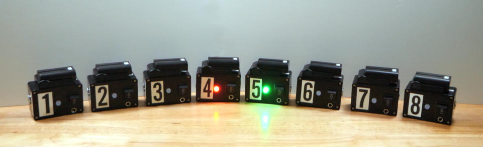
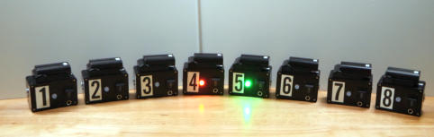
DIY ATEM TALLY EXTREME SYSTEM
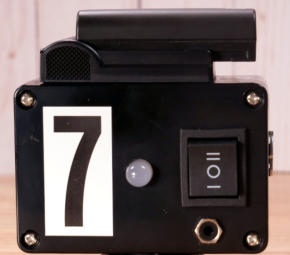
The DIY ATEM TALLY EXTREME SYSTEM consists of any number of TALLY MODULES that monitor the camera selections on Blackmagic Design ATEM video switchers. These modules use the popular Sony style NP batteries for power and connect to your ATEM via WiFi. Only module number 1 connects to the ATEM and all subsequent modules then listen to the module before it. This means that the entire system uses only one of the 5 available web connections on the ATEM. This frees up these other connections for things like a Hyperdeck, separate computers running the ATEM software control for operations such as graphics and audio, and for another computer running the Bitfocus Companion for the Elgato Streamdeck.


WATCH THE INTRO VIDEO
DIY ATEM TALLY EXTREME POWER RELAY
MODULE
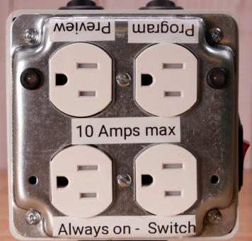
The Power Relay Module plugs into a wall outlet. One set of outlets is always on. The other outlets are controlled by the status of a Tally Module. When the Tally Module is in Preview mode the Preview outlet is turned on. When the Tally Module in in Program mode the Program outlet is turned on. These two outlets are isolated electrically buy using opto-isolated relays. The Power Relay Module can be several thousands of feet away from the controlling Tally Module but connected with ethernet or TRRS cable. The max power available in total from the Power Relay module is 1200 watts.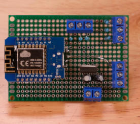
DIY ATEM TALLY MODULE
CIRCUIT BOARD
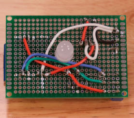
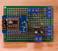
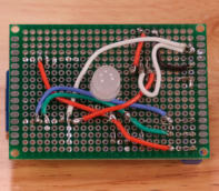
Get detailed video instructions on how to build the DIY ATEM TALLY MODULE CIRCUIT BOARD. Step by step guide to assembling, wiring and soldering each component onto the two sided circuit board.
DIY ATEM TALLY MODULE
REMOTE LED
Learn how to build and connect the REMOTE LED to the Tally Module. The RemoteLED can be controlled thousands of feet away from the Tally Module using TRRS or ethernet cabling. Place the Remote LED anywhere that will help the camera operator see his or her cues. The photo to the left shows the Remote LED mounted on the top of an external camera monitor with the Tally Module mounted off to the left of the camera.“STAND BY” AND “ON AIR” LED
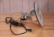
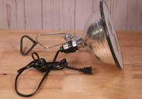
LIGHTS
Build your own “Stand By”” and “On Air” notification lights using green and red LED bulbs. These lights are eight and a half inches in diameter and use standard household colored LED bulbs that draw only three and a half watts each. They plug into the DIY ATEM TALLY EXTREME POWER RELAY MODULE. The “Stand By” light plugs into the Preview socket and the “On Air” light plugs into the Program outlet. Ethernet or TRRS cable connects the Tally Module to the Power Relay Module which can be thousands of feet away.

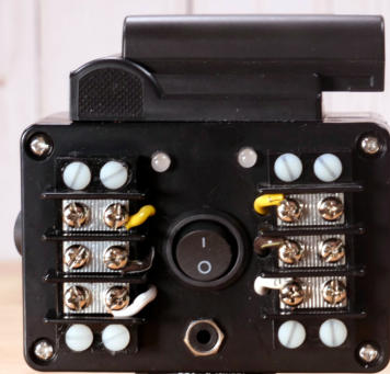
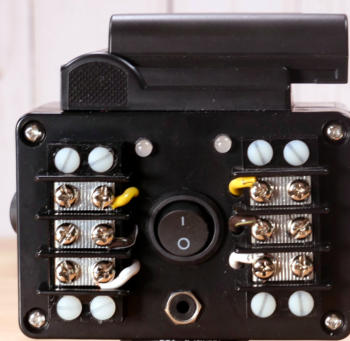
DIY ATEM TALLY EXTREME RELAY
MODULE
The Relay Module is powered by a NP style battery. The terminal blocks are connected to internal opto-isolated relays and their status is determined by a connected Tally Module. When the Tally Module is in Preview mode the Preview relay is turned on. When the Tally Module in in Program mode the Program relay is turned on. The Relay Module can be several thousands of feet away from the controlling Tally Module but connected with ethernet or TRRS cable. Both sets of terminal blocks provide common, normally open and normally closed contacts. The max current the relays can handle is 10 amps. The Relay Module is useful for controlling sound effects, lighting or other events that need triggering.PURCHASE YOUR OWN SET OF
CONSTRUCTION PLANS HERE
Many hundreds of hours went into the research, design and developing the constructions plans. You will receive PDF documents detailing the complete build list with links for purchasing them. You will also receive complete schematic diagrams of each module. More than six and a half hours of detailed, step by step video instruction is also included. When your payment is received and verified an email will be sent to you with a download link to our DropBox account within 24 hours.. Video Segments 1 through 6 are for the Tally Module. Video Segment 7 is for the Power Relay Module and video Segment 8 is for the Relay Module. Please feel free to contact us with any questions you may have.
Copyright 2021 ATEMtallyEXTREME.com All rights reserved.
DIY ATEM TALLY EXTREME SYSTEM
The DIY ATEM TALLY EXTREME SYSTEM consists of any number of TALLY MODULES that monitor the camera selections on Blackmagic Design ATEM video switchers. These modules use the popular Sony style NP batteries for power and connect to your ATEM via WiFi. Only module number 1 connects to the ATEM and all subsequent modules then listen to the module before it. This means that the entire system uses only one of the 5 available web connections on the ATEM. This frees up these other connections for things like a Hyperdeck, separate computers running the ATEM software control for operations such as graphics and audio, and for another computer running the Bitfocus Companion for the Elgato Streamdeck.


WATCH INTRO VIDEO
DIY ATEM TALLY MODULE
CIRCUIT BOARD
Get detailed video instructions on how to build the DIY ATEM TALLY MODULE CIRCUIT BOARD. Step by step guide to assembling, wiring and soldering each component onto the two sided circuit board.
DIY ATEM TALLY MODULE
REMOTE LED
Learn how to build and connect the REMOTE LED to the Tally Module. The RemoteLED can be controlled thousands of feet away from the Tally Module using TRRS or ethernet cabling. Place the Remote LED anywhere that will help the camera operator see his or her cues. The photo to the left shows the Remote LED mounted on the top of an external camera monitor with the Tally Module mounted off to the left of the camera.DIY ATEM TALLY EXTREME POWER
RELAY MODULE
The Power Relay Module plugs into a wall outlet. One set of outlets is always on. The other outlets are controlled by the status of a Tally Module. When the Tally Module is in Preview mode the Preview outlet is turned on. When the Tally Module in in Program mode the Program outlet is turned on. These two outlets are isolated electrically buy using opto-isolated relays. The Power Relay Module can be several thousands of feet away from the controlling Tally Module but connect with ethernet or TRRS cable. The max power available in total from the Power Relay module is 1200 watts.“STAND BY” AND “ON AIR” LED
LIGHTS
Build your own “Stand By”” and “On Air” notification lights using green and red LED bulbs. These lights are eight and a half inches in diameter and use standard household colored LED bulbs that draw only three and a half watts each. They plug into the DIY ATEM TALLY EXTREME POWER RELAY MODULE. The “Stand By” light plugs into the Preview socket and the “On Air” light plugs into the Program outlet. Ethernet or TRRS cable connects the Tally Module to the Power Relay Module which can be thousands of feet away.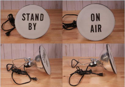
DIY ATEM TALLY EXTREME RELAY
MODULE
The Relay Module is powered by a NP style battery. The terminal blocks are connected to internal opto-isolated relays and their status is determined by a connected Tally Module. When the Tally Module is in Preview mode the Preview relay is turned on. When the Tally Module in in Program mode the Program relay is turned on. The Relay Module can be several thousands of feet away from the controlling Tally Module but connected with ethernet or TRRS cable. Both sets of terminal blocks provide common, normally open and normally closed contacts. The max current the relays can handle is 10 amps. The Relay Module is useful for controlling sound effects, lighting or other events that need triggering.PURCHASE YOUR OWN SET OF
CONSTRUCTION PLANS HERE
Many hundreds of hours went into the research, design and developing the constructions plans. You will receive PDF documents detailing the complete build list with links for purchasing them. You will also receive complete schematic diagrams of each module. More than six and a half hours of detailed, step by step video instruction is also included. When your payment is received and verified an email will be sent to you with a download link to our DropBox account within 24 hours.. Video Segments 1 through 6 are for the Tally Module. Video Segment 7 is for the Power Relay Module and video Segment 8 is for the Relay Module. Please feel free to contact us with any questions you may have.
Copyright 2021 ATEMtallyEXTREME.com All rights reserved.